
A Little History
UART stands for Universal Asynchronous Receiver/Transmitter — "asynchronous" is the operative word, and it's the whole idea. The concept dates back to telegraphy and teletypes, long before integrated circuits existed: two parties agree on a signaling rate ahead of time, and after that, no shared clock wire is needed to stay in sync for the duration of one character.
That same idea carried straight through into computing via RS-232 serial ports — the chunky beige connectors on the back of every PC through the 1980s and 90s, used for modems, mice, and terminals. The physical connector mostly disappeared, but the protocol underneath it didn't go anywhere: it just moved onto a couple of GPIO pins.
What It's Actually For
UART is the "hello, are you there?" of embedded electronics. It's usually the very first interface a new board gets, because it needs no special hardware beyond two wires and a common ground — no bus arbitration, no addressing scheme, nothing to configure except a baud rate both ends agree on. That makes it the default choice for debug consoles, GPS modules, Bluetooth serial modules, and countless simple point-to-point links. If a product has a "serial debug port," it's almost certainly UART underneath.
How It Works
The line idles HIGH. To send a byte, the transmitter pulls the line LOW for one bit period — the start bit — which is the only signal a receiver gets that something is coming. Eight data bits follow, sent first, each held for exactly one bit period. A stop bit (the line returning HIGH) closes out the frame. There is no clock line, no acknowledgment, and no error correction — the whole scheme depends on both ends having agreed on the bit period (the baud rate) beforehand.
To measure an unknown baud rate from a raw capture: find the narrowest pulse in the signal (that's one bit period) and take its reciprocal. A ~104µs pulse means 1 ÷ 0.000104 ≈ 9600 baud.
On the Sniffer Board
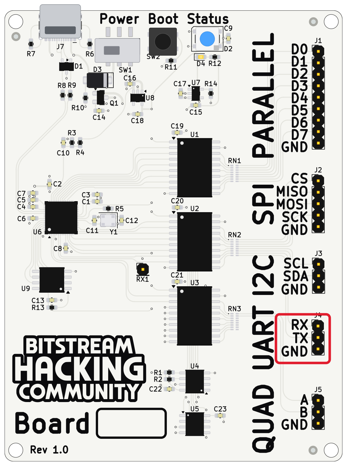
| Pin | Connects to |
|---|---|
| RX | Not used — leave unconnected (it's an input to the board) |
| TX | Logic analyzer channel D0 |
| Logic analyzer ground clip |
9600 baud, 8 data bits, no parity, 1 stop bit (8N1) — standard and unremarkable. In PulseView: 1 MHz sample rate, 5 second capture gives roughly 100× oversampling, comfortably clean for the UART decoder to lock onto. Add the decoder (Decode → Add a protocol decoder → UART), assign RX = D0, and set the baud/data/parity/stop fields above.