A Little History
I²C — "Inter-IC," pronounced "eye-squared-C" — was designed by Philips (now NXP) in 1982 to solve a problem inside their own television sets: too many chips needed to talk to each other, and every point-to-point connection between them meant more wires and more cost. I²C's pitch was that any number of chips could share just two wires, as long as each one had its own address. It worked well enough that it quietly became one of the most widely used buses in electronics, decades later.
What It's Actually For
Short-distance, low-speed communication between chips that live on the same board — sensors, real-time clocks, EEPROMs, small displays. Its whole value proposition is wire count: two shared lines can address dozens of devices, versus needing a dedicated pair (or more) per device. The tradeoff is speed and distance — I²C is not the bus you'd choose to move a lot of data quickly, or to run a signal any real distance.
How It Works
Both lines idle HIGH, held up by pull-up resistors — devices only ever pull the lines LOW, never drive them HIGH themselves (this is what lets multiple devices share the bus safely). A transaction opens with a START condition: SDA falls while SCL is still HIGH — the one moment where SDA is allowed to change while SCL isn't toggling, which is exactly what makes it recognizable as "start," not just another data bit. The controller then clocks out a 7-bit address and a read/write bit, and the addressed device pulls SDA low for one clock to that it's listening. Data bytes follow the same pattern — 8 bits, then an ACK — until the controller ends the transaction with a STOP condition: SDA rising while SCL is HIGH.
On the Sniffer Board
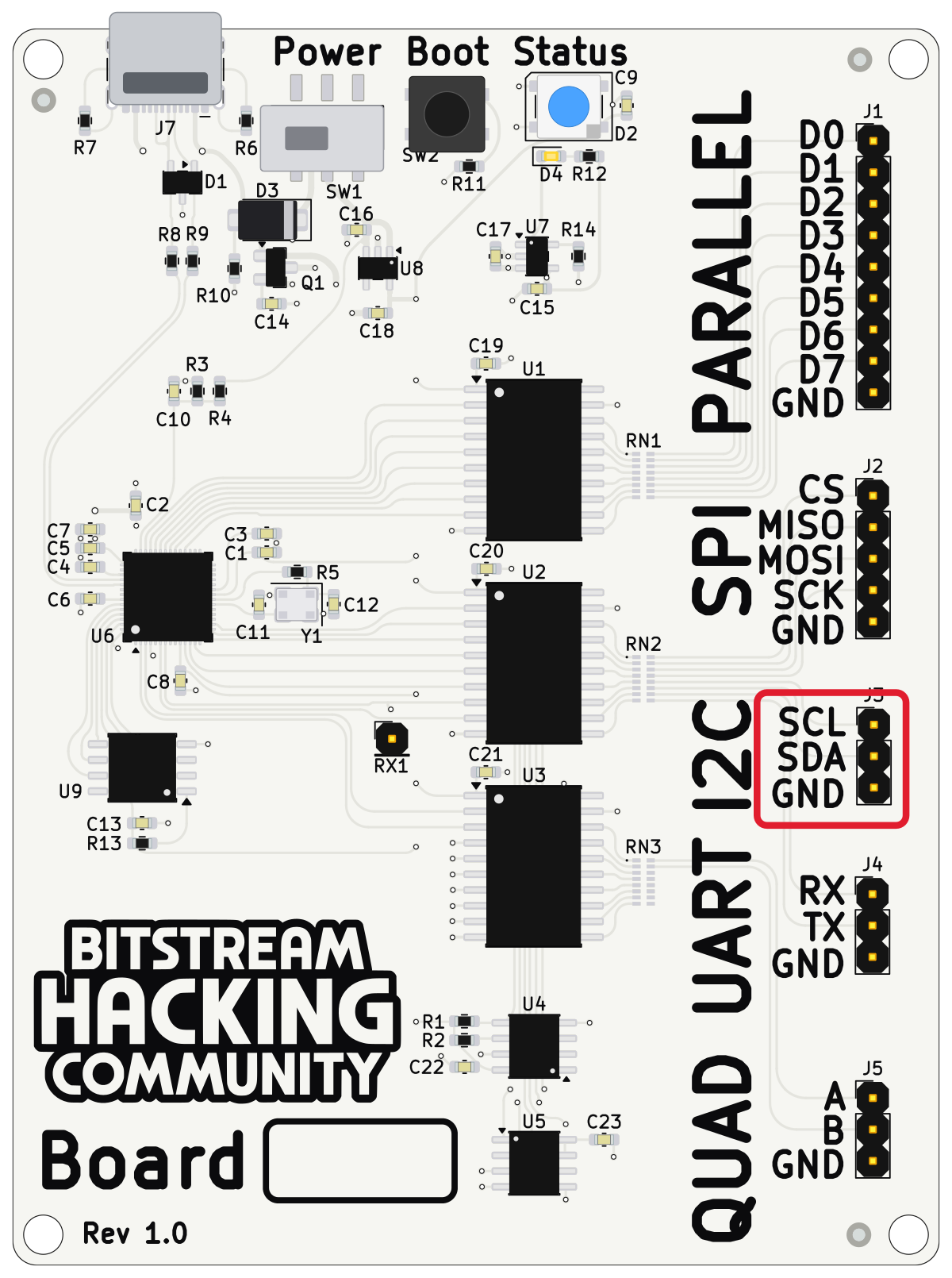
One device sits on the sniffer board's I²C bus: a small EEPROM. Its memory is split into 256-byte blocks and each block answers at its own address, so expect to see the controller talk to more than one address.
| Pin | Connects to |
|---|---|
| Logic analyzer channel D0 | |
| Logic analyzer channel D1 | |
| Logic analyzer ground clip |
100 kHz standard mode. In PulseView: 4 MHz sample rate, 2 second capture (about 40× oversampling). Add the I²C decoder, assign SCL = D0 and SDA = D1 — bit rate is auto-detected from the capture.