
A Little History
Quadrature encoding predates digital electronics — it's a mechanical trick for telling rotation direction from two sensors instead of one. Industrial tachometers and rotary encoders have used it for decades. It became a household technology (literally) inside the opto-mechanical computer mouse: a rubber ball turning two small wheels, each interrupting a pair of light beams slightly out of phase with each other — exactly the same signal shape you'll see on the QUAD header.
What It's Actually For
Measuring rotation — direction and amount — without an absolute position sensor. A single square wave from a spinning shaft tells you how fast, but not which way. Add a second channel offset by a quarter cycle, and the order the two edges arrive in tells you the direction, while simply counting edges tells you how far it turned. It's still the standard way rotary encoders — volume knobs, motor shaft feedback, old-school mice — report motion today.
How It Works
Two channels, A and B, run the same square wave frequency, offset by a quarter period (90°). Whether A leads B or B leads A depends on which direction things are turning — reverse the rotation and the two channels swap which one leads. On the sniffer board this relationship is fixed and just keeps repeating; there's no rotation to reverse, it's simply here as a known-good pattern to test against.
On the Sniffer Board
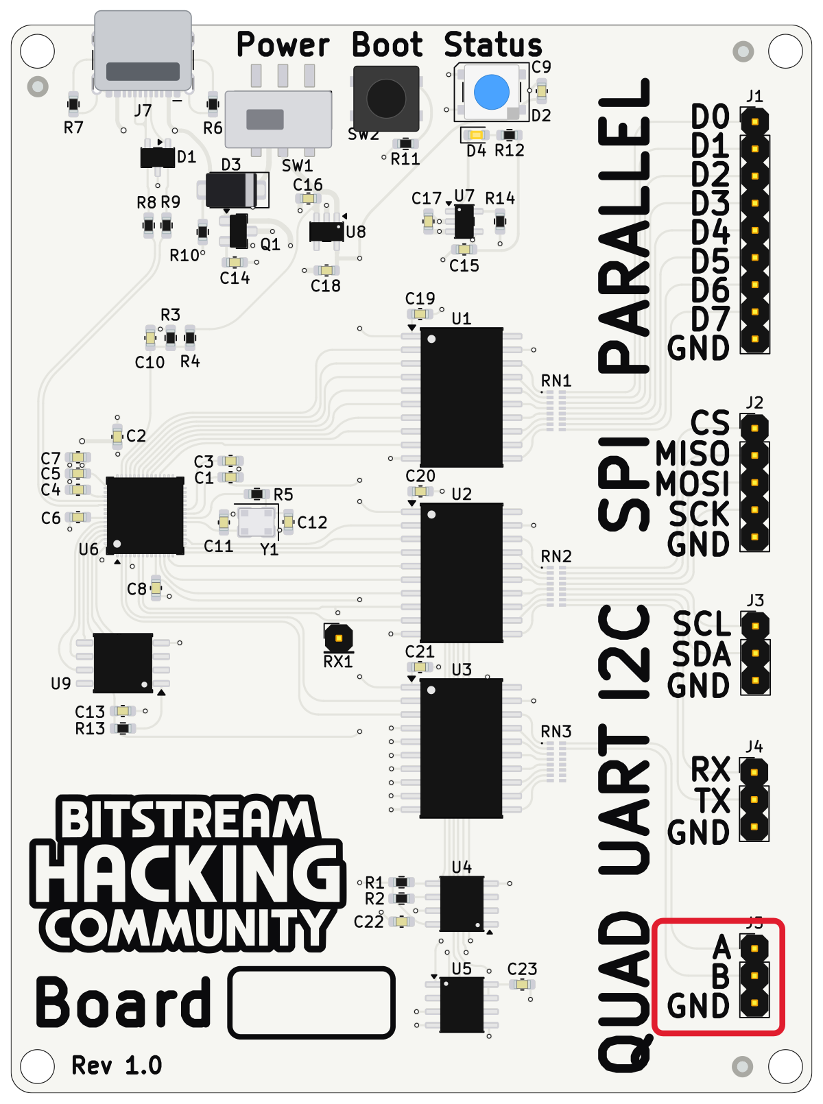
| Pin | Connects to |
|---|---|
| A | Logic analyzer channel D0 |
| B | Logic analyzer channel D1 |
| Logic analyzer ground clip |
In PulseView: 1 MHz sample rate, 200 ms capture, then click Run. You should see two clean square waves at roughly 1 kHz, with B trailing A by a quarter period.
- A and B look identical? Both clips are probably on the same pin — recheck.
- B leads A instead of lagging? Swap the D0/D1 clips.
- Noise or nothing at all? Check the ground connection first — it's the most common miss.