A Little History
Parallel buses are older than serial protocols, in a sense — early computers moved data on wide buses because it was the obvious way to go fast when clock speeds were low: if you can't toggle a wire quickly, use more wires instead. The Centronics printer port, ISA and early PCI expansion buses, and camera and LCD interfaces on countless embedded devices all work this way. Serial protocols like UART, I²C, and SPI became more common as clock speeds rose high enough that shifting bits out one at a time stopped being the bottleneck — but wherever raw throughput still matters more than pin count, parallel buses never really left.
What It's Actually For
Moving a lot of data with the simplest possible per-bit circuitry. There's no shift register needed on either end — every bit just needs its own wire and something willing to hold a voltage on it. The cost is obvious: 8 bits of parallel data needs 8 pins, versus 1 or 2 for a serial protocol. That trade only makes sense when pins are cheap relative to the speed you need, which is why parallel buses show up on memory interfaces and camera sensors far more often than on simple sensors.
How It Works
All 8 lines present a full byte's worth of voltage levels simultaneously, hold it stable for a fixed window, then change all at once to the next byte. There's no clock line and no strobe signal telling the receiver when to sample — the stable window itself is the framing. As long as both sides agree on the timing, the receiver just samples the middle of each window and ignores the brief chaos during a transition.
On the Sniffer Board
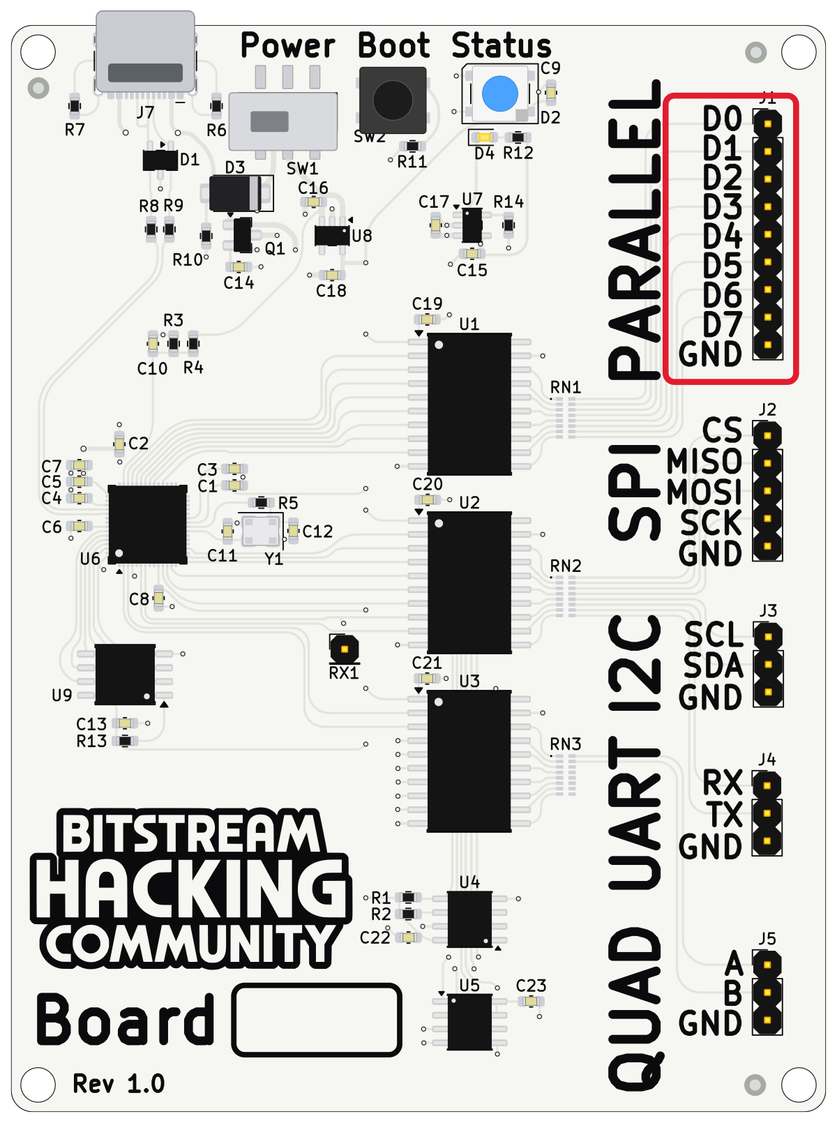
Each byte holds stable on D0–D7 for exactly 5 ms, then every line changes at once. Because this uses all 8 analyzer channels simultaneously, it can't be captured alongside any other bus on the sniffer board — plan on a separate capture just for this one.
| Pin | Connects to |
|---|---|
| D0–D7 | Logic analyzer channels D0–D7 (D7 = ) |
| Logic analyzer ground clip |
In PulseView: 100 kHz sample rate, 10 second capture — that gives around 500 samples per 5 ms window, comfortably more than enough to land well clear of a transition edge. No decoder is needed here: enable all 8 channels, zoom into one stable window, and read the byte value directly off the levels — D7 is the , D0 is the .