A Little History
SPI — Serial Peripheral Interface — came out of Motorola in the 1980s, alongside their 68000-series microcontrollers. Unlike I²C, it was never formally standardized by any committee; it just became the de facto convention because it was simple to implement in hardware and fast enough to matter. That informal history is exactly why SPI has quirks like four numbered "modes" rather than one fixed behavior — different manufacturers settled on slightly different conventions before anyone was enforcing one.
What It's Actually For
Fast, short-distance, chip-to-chip communication where wire count is cheap but speed matters — flash memory, SD cards, ADCs/DACs, small displays. Where I²C trades speed for wire count, SPI makes the opposite bet: more wires (four instead of two), but no addressing overhead and a clock rate that can run into the tens of MHz. Adding a second device just means giving it its own CS line — the clock and data lines are shared.
How It Works
The controller drives CS (chip select) LOW to begin talking to a specific peripheral — there's no start condition or address byte, CS itself is the framing. While CS is low, the controller toggles SCK, and on each clock edge one bit moves in each direction at once: the controller drives MOSI — Controller Out, Peripheral In, though the letters actually come from the original name, Master Out Slave In — while the peripheral simultaneously drives MISO (Master In Slave Out, Controller In / Peripheral Out). Older datasheets and some parts still use the original names; newer ones favor controller/peripheral, but the pin names MOSI/MISO stuck around either way. This is what makes SPI full-duplex — unlike UART or I²C, both sides are always sending, whether or not either side has anything meaningful to say.
On the Sniffer Board
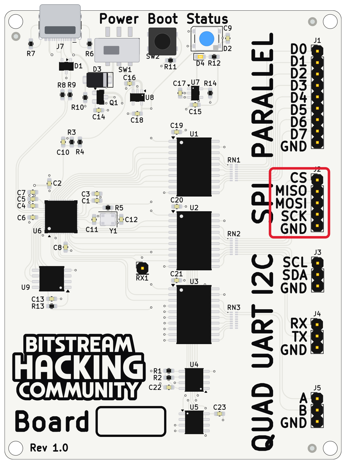
The SPI peripheral here is a real EEPROM. The controller sends a read command on MOSI — an opcode byte plus a two-byte address — and the EEPROM answers on MISO with the requested data. All four wires need to be captured to see the full exchange: the first few bytes on MOSI are the read command, and the interesting content is on MISO afterward.
| Pin | Connects to |
|---|---|
| CS | Logic analyzer channel D0 |
| MISO | Logic analyzer channel D1 |
| MOSI | Logic analyzer channel D2 |
| SCK | Logic analyzer channel D3 |
| Logic analyzer ground clip |
Mode 0 (CPOL=0, CPHA=0 — data sampled on the rising clock edge), -first, CS active LOW, 100 kHz. In PulseView: 4 MHz sample rate, 2 second capture. Add the SPI decoder, assign CS# = D0, MISO = D1, MOSI = D2, CLK = D3 (PulseView's name for the header's SCK pin), and set CS# polarity to active low.