What You'll Need
- A soldering iron with a fine tip, and thin solder
- Tweezers, for placing the tiny parts
- Optional: flux, which helps with the EEPROM's close-set pins (the solder already has some in its core)
- A breadboard, to hold the pin headers straight while you solder them (we can lend you one)
- Optional: isopropyl alcohol and an old toothbrush, to clean off flux
We don't supply irons or solder: head to the Hardware Hacking community, which has soldering gear set up. We do have a few breadboard jigs for the pin headers. Ask at our booth if you'd like one, and please bring it back when you're done.
Level 1 Minibadge
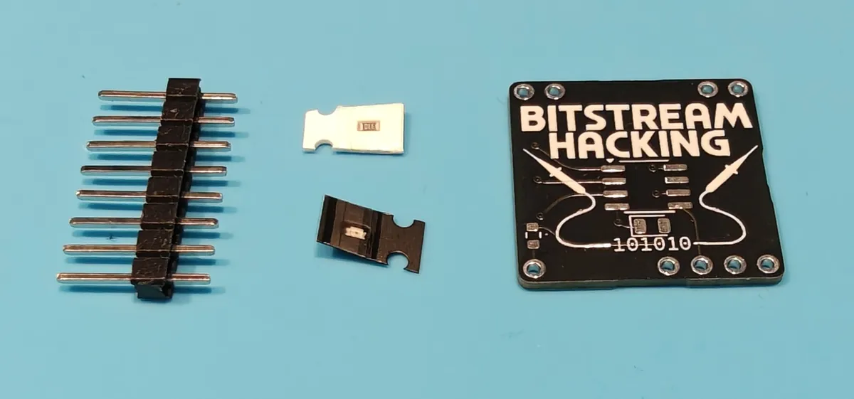
The kit: two 8-pin header strips, the LED, the resistor and the board.
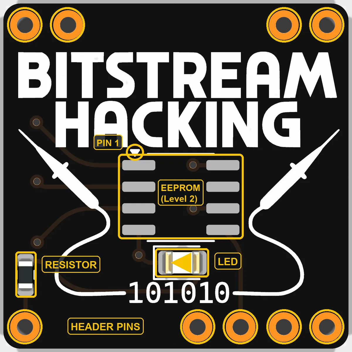
What goes where:
-
Tell the two small parts apart
The resistor is black with
330printed on it. It doesn't matter which way round it goes. The LED is the white one, and it only works one way round, so the next step is about which way that is. Its colour is a surprise: it lights red, yellow, green or blue.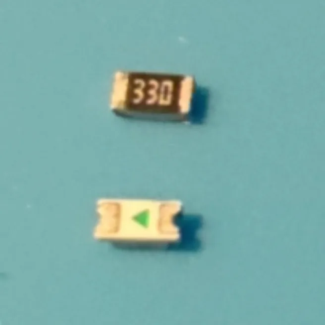
Resistor (top) and the LED's underside (bottom). -
Work out which way the LED goes
Flip the LED over: its underside has a green triangle, and the triangle points to the LED's negative end (the cathode).
Now look at the board with BITSTREAM HACKING reading the right way up. The LED's two pads sit just above
101010, inside a white bracket that's closed on the left. The LED goes on with its triangle pointing left, toward the closed end.Since the triangle ends up underneath, set the LED down upside down with the triangle pointing left, then flip it top edge over bottom edge. That keeps the triangle pointing left.
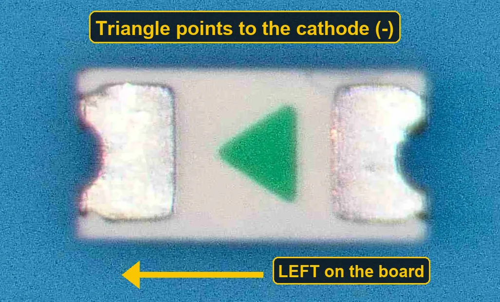
The LED's underside: the triangle points to the cathode, and it points left once the LED is on the board. 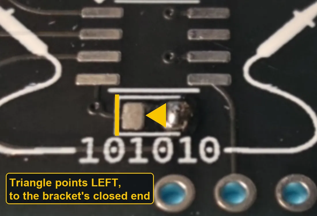
On the board: the bracket's closed left end (highlighted) is where the triangle points. -
Tin one pad for each part
Melt a small blob of solder onto one pad of each part. It doesn't matter which pad; what matters is that only one of each pair gets solder for now. The photo uses the right-hand LED pad and the lower resistor pad.
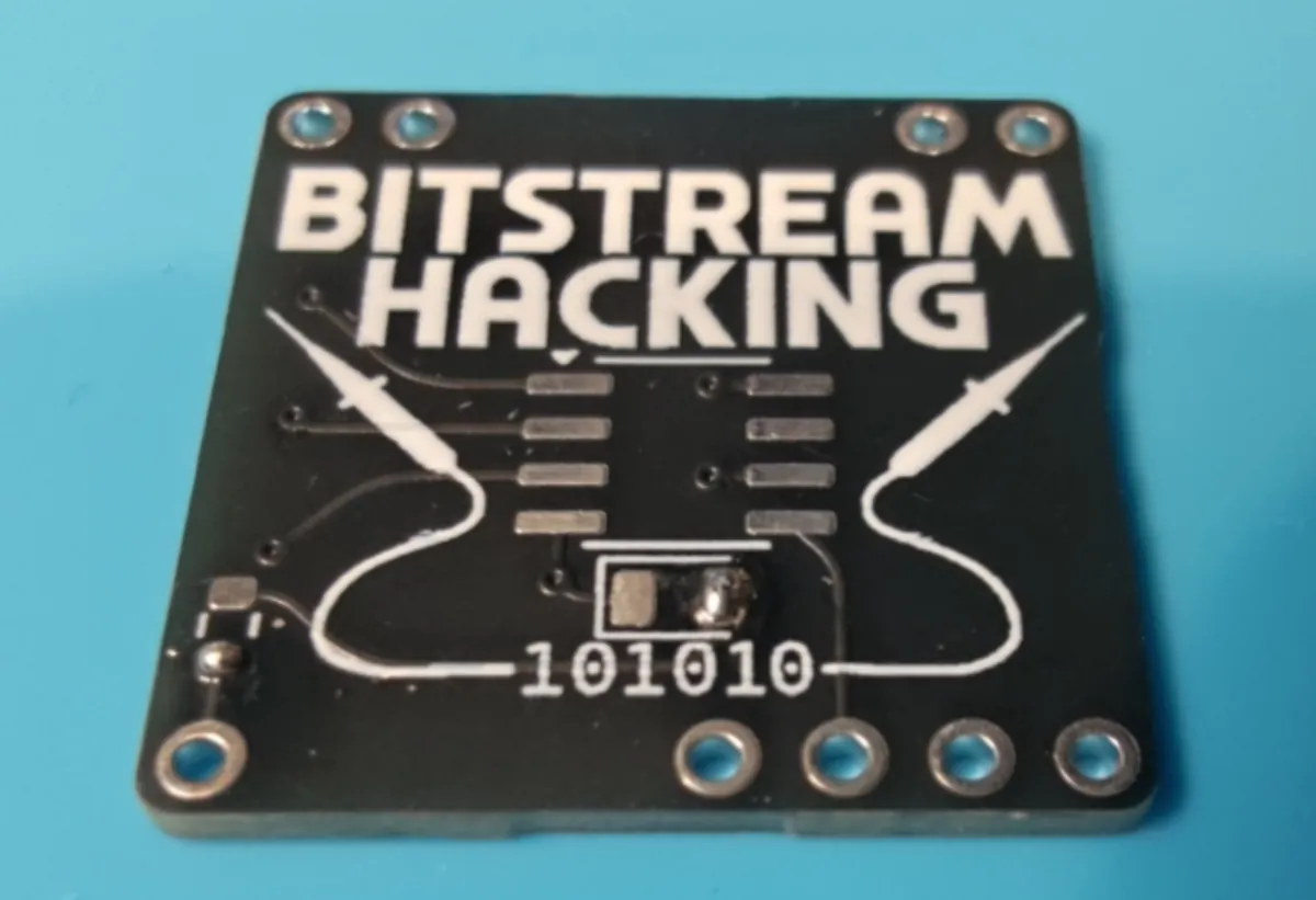
One pad tinned for the LED and one for the resistor. -
Tack each part down by one end
Hold the part in place with tweezers, touch the iron to the tinned pad until the solder melts, and slide the part into it. Take the iron away and hold the part still for a second. Check it sits flat and straight across both pads; if not, reheat that joint and nudge it.
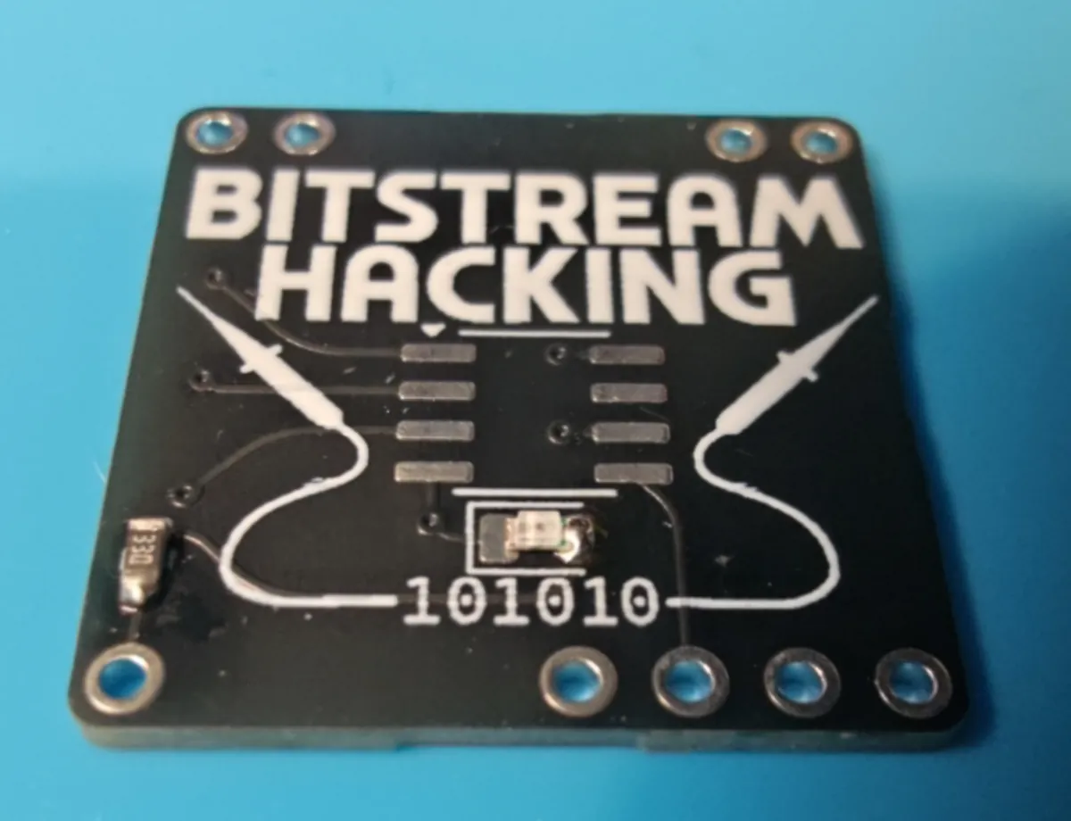
Both parts tacked by one end. -
Solder the other ends
Solder the free end of each part. A good joint is shiny and wets both the part and the pad. Go back and touch up the first end too, if it looks lumpy.
Good: shiny, and slopes smoothly from the pad up the end of the part. Too much: a ball that hides the part's end. Touch it with a clean iron tip to wick some off. Too little: dull, or sitting on the pad without climbing the part. Reheat and add a touch more solder. 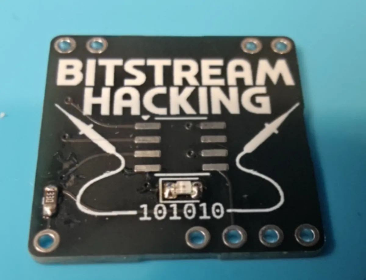
LED and resistor done. -
Set up the headers in a breadboard
Snap the two header strips into four pieces: two 2-pin pieces, one single pin and one 4-pin piece. Push them, long pins down, into a breadboard where the board's holes will land: the two pairs under the top corners, and the single pin and the 4-pin piece along the bottom edge. Then drop the board on, face up, so every short pin pokes up through a hole. The breadboard keeps the pins straight and evenly spaced while you solder.
No breadboard? We have some you can borrow at the booth. Please bring it back when you're done.
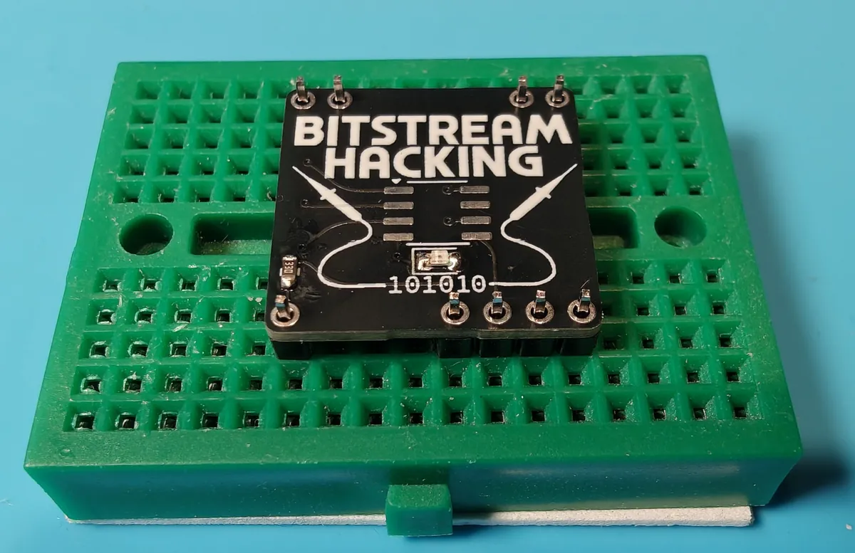
Nine pins through nine holes: 2 + 2 along the top, 1 + 4 along the bottom. -
Solder the header pins
Solder each pin from the top. Heat the pin and the ring around it together, then feed in solder until it flows all the way round into a small cone. Then pull the badge out of the breadboard.
Don't hold the iron on a pin for long: a few seconds is plenty. Heat runs down the pin, and too much will soften the header's plastic or melt the breadboard. If a joint isn't flowing, take the iron away, let it cool and try again.
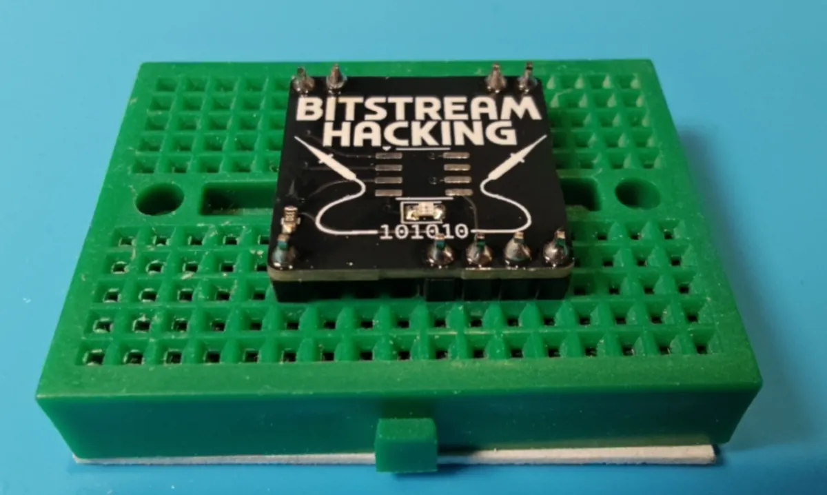
That's the Level 1 minibadge done.
The empty pads in the middle are for the EEPROM chip. You get that when you solve Level 1. The LED only lights in a SAINTCON conference badge (see How It Works), so don't worry if it stays dark at our booth.
Level 2 Minibadge: Add the EEPROM
The chip is an M24C08 EEPROM in an 8-pin SOIC package. Its legs are much closer together than anything on the Level 1 kit, so take it slow. Extra flux helps if there's some around, but you don't need it: the solder already has flux in its core.
Leave the three solder jumpers on the back of the board alone. They set the chip's I2C address, and bridging them can move it somewhere the checker won't look.
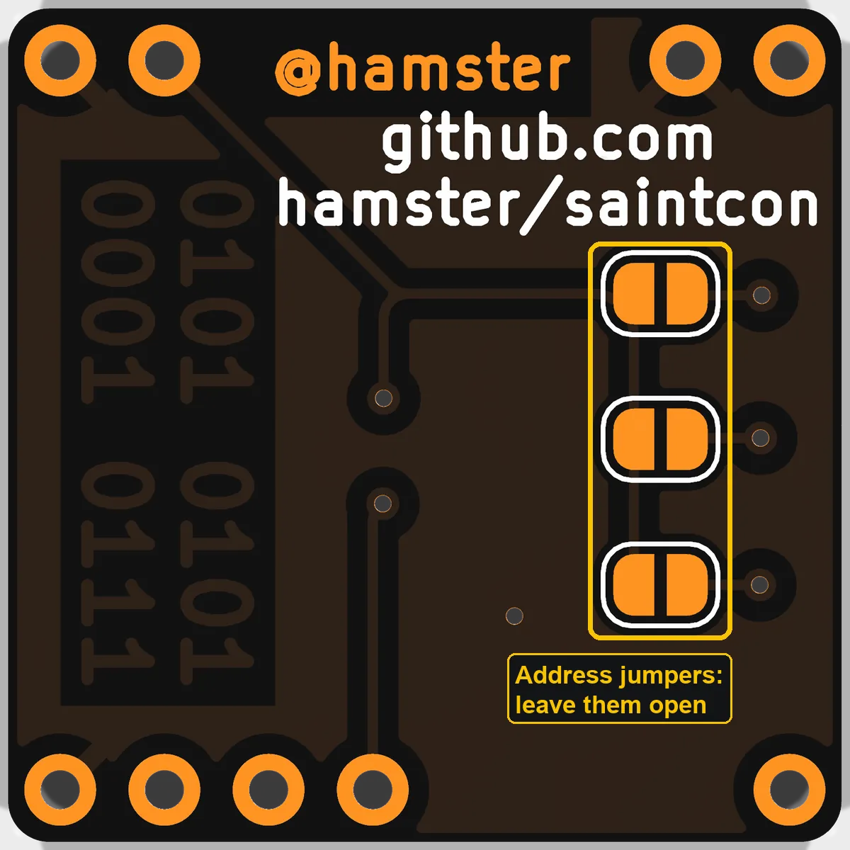
-
Find pin 1
On the board, a small white triangle above the top-left pad marks pin 1. On the chip, go by the writing and the logo: turn the chip so they read the normal way up, and pin 1 is the bottom-left leg. Then give it a quarter turn so the writing runs top to bottom, as in the photo: pin 1 is now top left, next to the board's triangle.
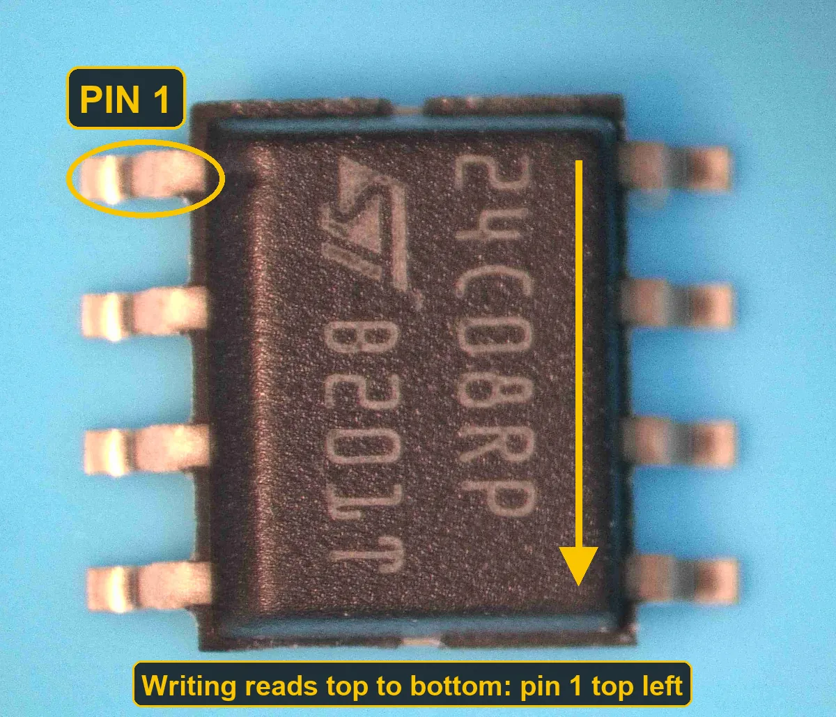
Turned the way it goes on the board: the writing reads top to bottom, and pin 1 is top left. 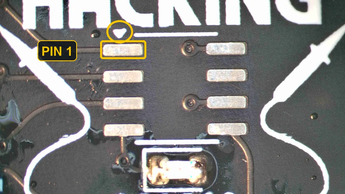
The white triangle marks pin 1's pad (top left). -
Tin one corner pad
Melt a small blob of solder onto one corner pad. Any corner works; the photo uses the bottom right.
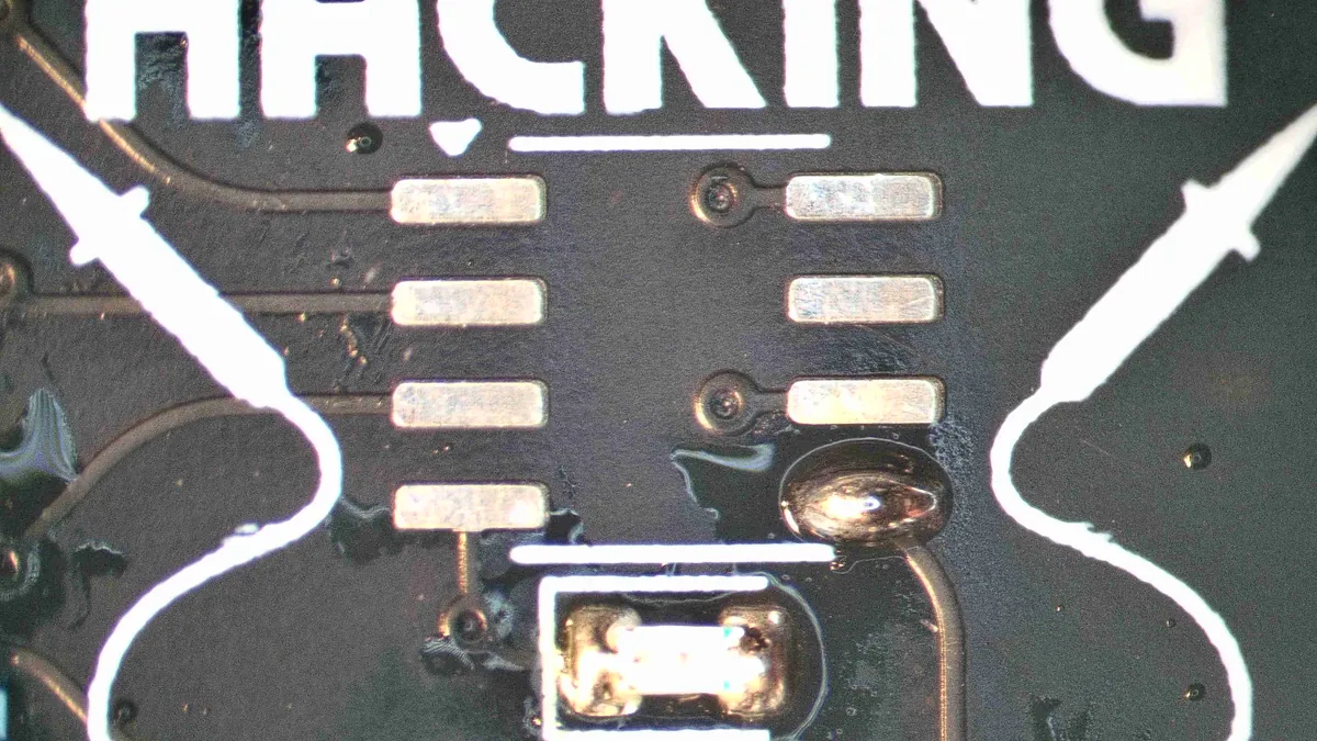
Bottom-right pad tinned. -
Tack the chip by that one leg
Hold the chip with tweezers, the right way round, and lay it on the pads. Reheat the tinned pad so its leg drops into the solder. Before going further, check that all eight legs sit in the middle of their pads and the chip is flat. If it's off, reheat that one leg and nudge it.
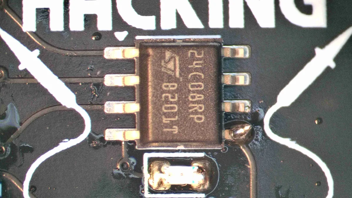
Tacked by one leg, every leg centred on its pad. -
Solder the other seven legs
Do the opposite corner next so the chip can't twist, then the rest. If you have flux, brush some on first: it makes the solder flow onto each leg and pull away from the gaps between them. Touch up the first leg at the end.
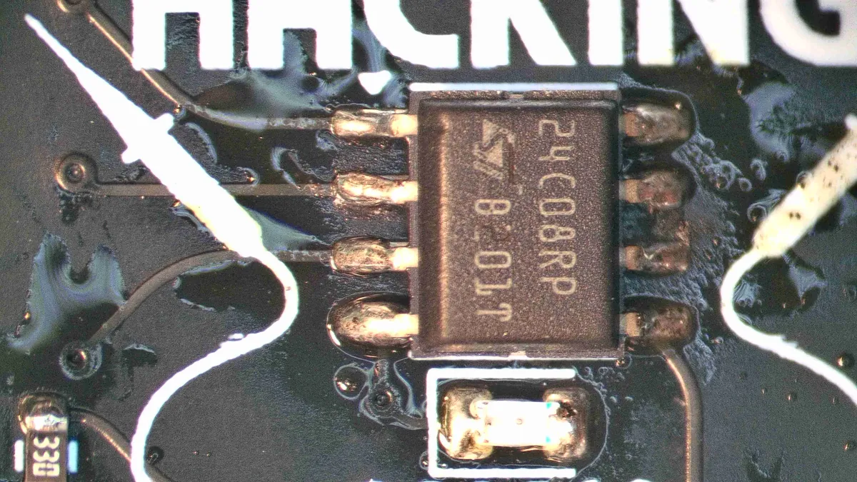
All eight legs soldered, flux still on. -
Check for bridges (and clean up if you can)
Cleaning is optional but a good idea: if there's isopropyl alcohol around, scrub the flux off with it and a toothbrush, which also makes the joints easier to inspect. Either way, look closely, with a magnifier if you have one, for solder joining two neighbouring legs. A bridge is the most common mistake. To clear one, drag a clean iron tip down between the legs (a dab of flux makes it easier, if you have some).
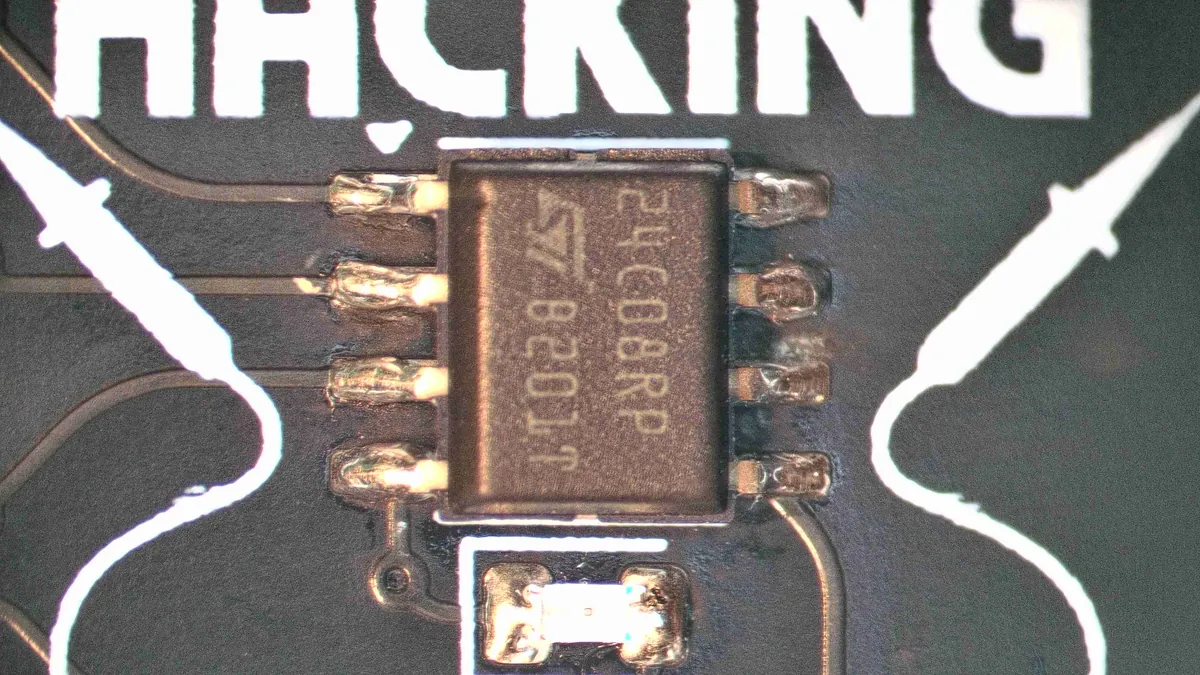
Cleaned: eight separate joints, nothing bridged.
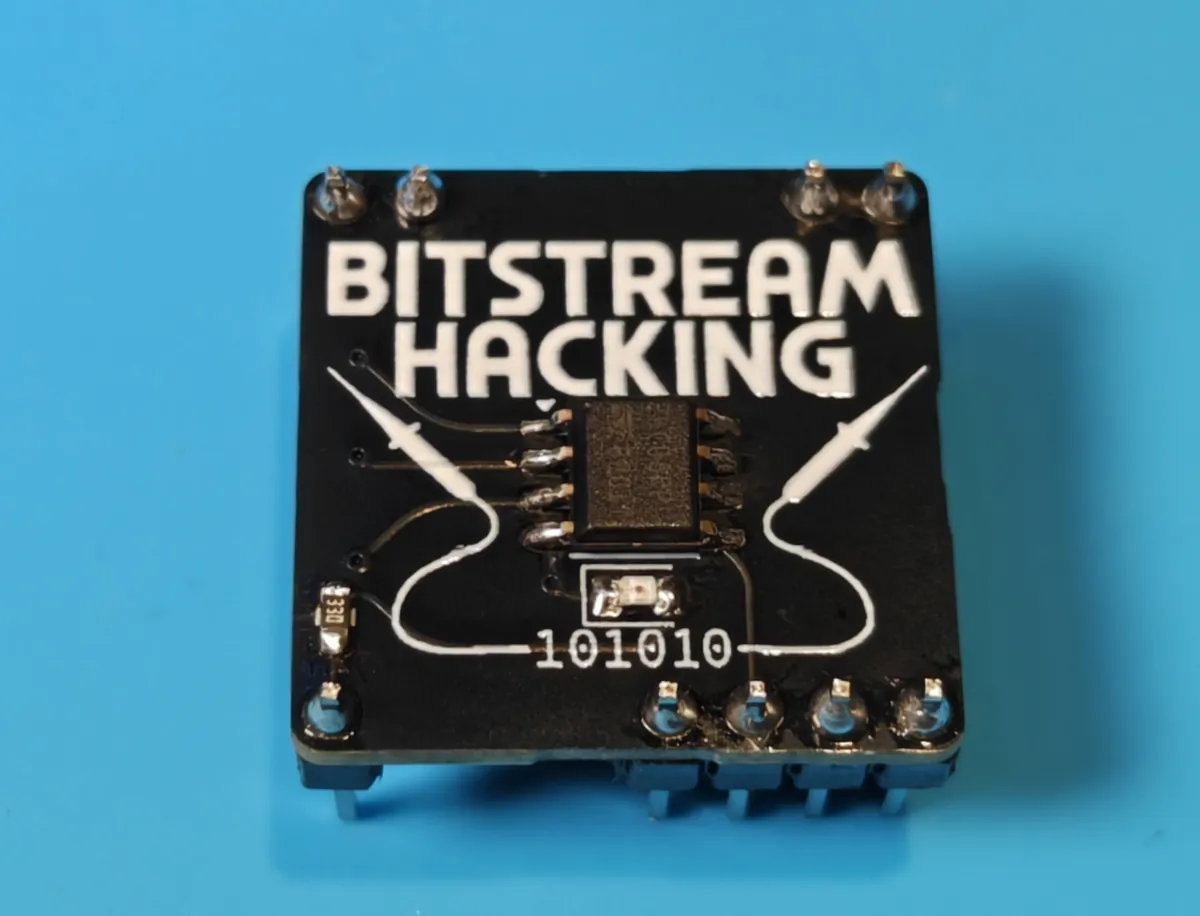
Next, prove your tools work: reading the blank chip is also your check that every leg is soldered properly.
How It Works
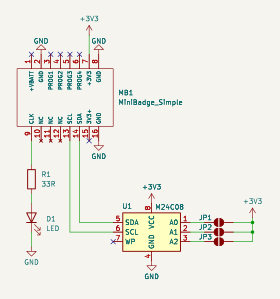
A minibadge plugs into the SAINTCON conference badge, which is its host. The conference badge gives it 3.3 V and ground, an I2C bus (SCL and SDA) and a CLK line. The LED and resistor hang off CLK, so the LED lights when the conference badge drives that pin. The EEPROM sits on the I2C bus, which is how the checker at our booth reads it.
The minibadge adapters at our booth and the checker don't connect CLK, so the LED stays dark in them. That's expected: plug it into a conference badge to see it light.